Human Orbital Spaceflights
![]()
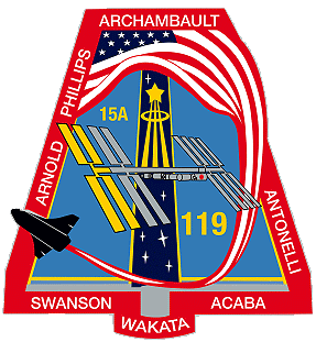
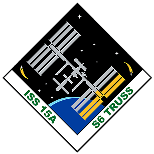
International Flight No. 261STS-119Discovery (36)125th Space Shuttle missionUSA |
 |
 |
![]()
Launch, orbit and landing data
walkout photo |
 |
|||||||||||||||||||||||||||||||||
alternative crew photo |
alternative crew photo |
|||||||||||||||||||||||||||||||||
alternative crew photo |
alternative crew photo |
|||||||||||||||||||||||||||||||||
alternative crew photo |
||||||||||||||||||||||||||||||||||
Crew
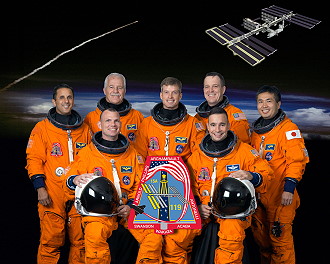
| No. | Surname | Given names | Position | Flight No. | Duration | Orbits | |
| 1 | Archambault | Lee Joseph "Bru" | CDR | 2 | 12d 19h 29m 41s | 202 | |
| 2 | Antonelli | Dominic Anthony "Tony" | PLT | 1 | 12d 19h 29m 41s | 202 | |
| 5 | Acaba | Joseph Michael | MS-1, EV-3 | 1 | 12d 19h 29m 41s | 202 | |
| 4 | Swanson | Steven Ray "Swanny" | MS-2, EV-1, FE | 2 | 12d 19h 29m 41s | 202 | |
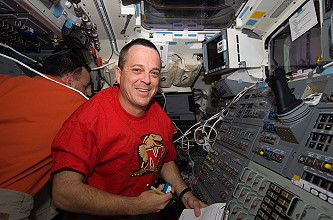
| 6 | Arnold | Richard Robert II "Ricky" | MS-3, EV-2 | 1 | 12d 19h 29m 41s | 202 | |
| 3 | Phillips | John Lynch | MS-4 | 3 | 12d 19h 29m 41s | 202 | |
| 7 | Wakata | Koichi | MS-5 | 3 | 137d 15h 04m 23s | 2166 |
Crew seating arrangement
|
 |
|
||||||||||||||||||||||||||||||||
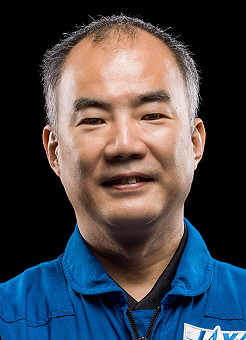
Backup Crew
|
 |
||||||||||
Hardware
| Orbiter : | OV-103 (36.) |
| SSME (1 / 2 / 3): | 2048-2 (9.) / 2051-2 (8.) / 2058-2 (4.) |
| SRB: | BI-135 / RSRM 103 |
| ET: | ET-127 (SLWT-33) |
| OMS Pod: | Left Pod 01 (39.) / Right Pod 03 (37.) |
| FWD RCS Pod: | FRC 3 (36.) |
| RMS: | 202 (12.) |
| EMU (launch): | EMU No. 3017 (PLSS No. 3017) / EMU No. 3006 (PLSS No. 1006) |
| EMU (landing): | EMU No. 3017 (PLSS No. 3017) / EMU No. 3004 (PLSS No. 1004) |
Flight
|
Launch from Cape Canaveral (KSC) and
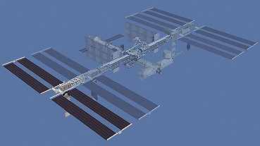
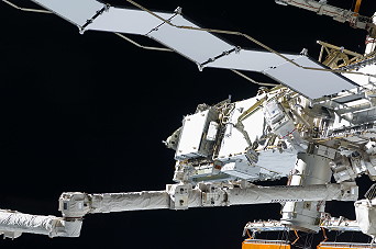
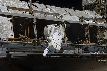
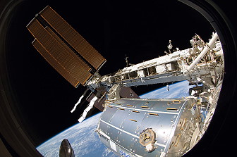
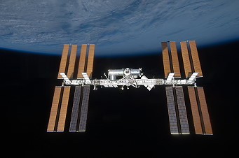
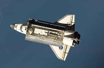
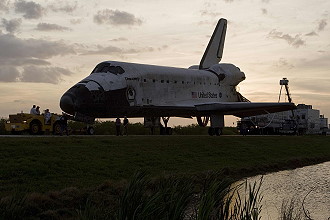
landing at Cape Canaveral (KSC), runway 15. The launch was scrubbed several times because of Shuttle problems in general with hydrogen flow control valves and then due to a leak in a liquid hydrogen vent line between the shuttle and the external tank. The result was the renounce of a planned fourth EVA during this mission, because the following Soyuz mission needed a docking port on the space station. STS-119 (ISS 15A ITS-S6) delivered and assembled the fourth starboard Integrated Truss Segment (S6), and the fourth set of solar arrays and batteries to the station. Koichi Wakata remained on the station, joining Expedition 18 Commander Michael Fincke and Flight Engineer Yuri Lonchakov. Koichi Wakata replaced Expedition 18 Flight Engineer Sandra Magnus, who returned to Earth with the STS-119 crew. Koichi Wakata served as a Flight Engineer for Expedition 18 and 19. Michael Fincke and Yuri Lonchakov were launched to the complex in the Soyuz TMA-13 spacecraft on October 12, 2008, from the Baikonur Cosmodrome in Kazakhstan. Koichi Wakata returned to Earth on shuttle mission STS-127, while Michael Fincke and Yuri Lonchakov returned in the Soyuz in April 2009. STS-119 delivered the International Space Station's final, major U.S. truss segment, Starboard 6 (S6), providing the power-generating capacity for a six-person crew to conduct increased science activities. With its two Solar Array Wings (SAWs) for converting solar energy into electrical power and a radiator for rejecting heat away from electrical components, the S6 is the final truss element and completes the station's 11-segment Integrated Truss Structure (ITS). Also called a Photovoltaic Module (PVM) because of its ability to generate, store and distribute electrical power to the station, the Starboard 6 segment will ensure the outpost is powered to its intended maximum potential. A unique feature about the S6 is that it will carry two spare Battery Charge/Discharge Units (BCDUs), used for controlling the charge and discharge of spare batteries on the station. The S6 segment was modified to carry the additional BCDUs, attached to the segment's Long Spacer Truss structure. The space station's solar arrays are the largest deployable space assemblies ever built and the most powerful electricity-producing arrays in orbit. Until deployed, each SAW remains folded in a special canister called a Solar Array Assembly (SAA) at the end of the S6 element. In the canister, each wing is equipped with an expandable mast. Two solar array blanket boxes, containing 32,800 solar cells, are connected to the ends of each canister and are restrained to the element frame for launch. The addition of S6 brings the station's total SAWs to eight. Each wing is 115 by 38 feet (35.1 by 11.6 meters) wide and, when all eight are fully deployed, will encompass an area of 32,528 square feet (3,022 square meters), minus the masts. The 310-foot (94.5 meters) integrated truss structure to which the S6 will be attached forms the backbone of the space station, with mountings for unpressurized logistics carriers, radiators, solar arrays, and the various elements. The 45-foot (13.7 meters) long S6 began as an operations test item for its twin sister, the Port 6 truss segment that was launched during Endeavour's STS-97 mission on November 30, 2000. The integrated truss segments started with Starboard 0 (S0) as the center assignment and were numbered in ascending order outward to the port (P) and starboard (S) sides. Starboard is the right side and port is the left side of the truss structure. Zenith (Z) is up, when the station is flying in its normal orientation. At one time, there was an S2 and a P2 planned, but they were eliminated when the station design was scaled back. From S0, the truss segments are P1, P3, P4, P5 and P6 and S1, S3, S4, S5 and S6. P6 is attached to P5, and once in orbit S6 was attached to S5. The S6 primary structure is made of a hexagonal-shaped aluminum structure and includes four bulkheads and six longerons, which are beams that connect the bulkheads. During the STS-119 mission, S6 was removed from the payload bay with the space station's robotic arm because the shuttle's arm is unable to remove the element with the current configuration of the station. The S6 element then was handed to the shuttle arm and maneuvered to another location, while the station arm changed base points. The S6 then was handed back to the station arm and maneuvered to an overnight park position. Removing the truss from the payload bay and maneuvering to an overnight park position took an entire day. The following day the truss was installed during a planned spacewalk. Once the final truss segment was attached, S6 supported power generation and energy storage, utility routing, power distribution and Orbital Replacement Unit (ORU) storage. Major subsystems of the S6 truss are the starboard outboard Photovoltaic Module (PVM), the Photovoltaic Radiator (PVR), the Long Spacer Truss (LST) and the Modified Rocketdyne Truss Attachment System (MRTAS). The S6 PVM includes all equipment outboard S5, namely the two Photovoltaic Array Assemblies (PVAAs) and the Integrated Equipment Assembly (IEA). The PVR provides thermal cooling for the IEA. The MRTAS is used to provide a structural interface to the S5 truss element. Each PVAA consists of a SAW and Beta Gimbal Assembly (BGA). S6 was the fourth and final of the four PVMs that convert sunlight to electricity in orbit. The primary functions of the power module are to collect, convert, store, and distribute electrical power to loads within the segment and to other station segments. Electrical power is a critical resource for the station because it allows astronauts to live comfortably, safely operate the station and perform complex scientific experiments. Since the only readily available source of energy for spacecraft is sunlight, technologies were developed to efficiently convert solar energy to electrical power. The PVMs use large numbers of solar cells assembled onto solar arrays to produce high power levels. NASA and Lockheed Martin developed a method of mounting the solar arrays on a "blanket" that can be folded like an accordion for delivery to space and then deployed to its full size once in orbit. The cells are made from purified crystal ingots of silicon that directly convert light to electricity for immediate use through a process called photovoltaics. Gimbals are used to rotate the arrays so that they face the sun to provide maximum power to the space station. After the conversion process, the PVMs also use the electricity to recharge onboard batteries for continuous sources of electricity while the station is in the Earth's shadow. Once complete, the station power system, consisting of U.S. and Russian hardware and four photovoltaic modules, will use between 80 - 100 kilowatts of power or about as much as 42 average houses (defined as 2,800 square feet (260.1 square meters) of floor space using 2 kilowatts each). Some of the electricity is needed to operate space station systems, but once that is figured in, the addition of the S6 will nearly double the amount of power available to perform scientific experiments on the station - from 15 kilowatts to 30 kilowatts. There are two SAWs on the S6 module, each deployed in the opposite direction of the other. Each SAW is made up of two solar blankets mounted to a common mast. Before deployment, each panel is folded accordion style into a Solar Array Blanket Box (SABB) measuring 20 inches (50.8 centimeters) high and 15 feet (4.6 meters) in length. Each blanket is only about 20 inches (50.8 centimeters) thick while in this stored position. The mast consists of interlocking battens that are stowed for launch inside a Mast Canister Assembly (MCA). When deployed by the astronauts, the SAW unfolds like an erector set. Like a human torso, it has two arms when mounted on S6, and they are rotated outwards by astronauts during a spacewalk so they can be fully deployed. Because these blankets were stored for such a long time, extensive testing was conducted to ensure they would unfold properly in orbit so the blankets would not stick together. When fully deployed, the SAW extends 115 feet (35.1 meters) and spans 38 feet (11.6 meters) across and extends to each side of the Integrated Equipment Assembly. Since the second SAW is deployed in the opposite direction, the total wing span is more than 240 feet (73.2 meters). Each SAW weighs more than 2,400 pounds (1,089 kg) and uses 32,800 solar array cells, each measuring 8 centimeters square with 4,100 diodes. The individual cells were made by Boeing's Spectrolab and Aviation Systems Engineering Co. There are 400 solar array cells to a string and there are 82 strings per wing. Each SAW is capable of generating 32.8 kilowatts, or about 10.5 to 15 kilowatts of usable power. There are two SAWs on the S6 module capable of delivering a combined 21 to 30 kilowatts of usable power per PVM with a total of four PVMs on the station. The solar arrays produce more power than can be made available to the station's systems and experiments. Because all or part of the solar arrays are eclipsed by the Earth or station structure at times, batteries are used to store electricity for use during those periods. About 60 percent of the electricity generated is used to recharge the batteries. During long eclipse periods, power availability is limited to about 10.5 kilowatts from each SAW, or 30 kilowatts per PVM. During shorter eclipse periods more power is available to station systems and experiments. Circuit breakers also regulate the flow of electricity to prevent overheating of the Utility Transfer Assembly (UTA) that allows power to flow through the rotating SARJ. When the S6 truss is attached to the S5 short spacer, it will be positioned outboard of the starboard SARJ, which is designed to continuously rotate to keep the S4 and S6 solar array wings oriented toward the sun as the station orbits the Earth. Located between S3 and S4, the starboard SARJ is a 10.5-foot (3.2 meters) diameter rotary joint that weighs approximately 2,500 pounds (1,134 kg). The SARJ can spin 360 degrees using bearing assemblies and a servo control system to turn. Due to vibrations and damage found on its race ring, the starboard SARJ has been rotated only when needed. STS-126 astronauts cleaned and lubricated the race ring, and preliminary results show the joint is moving more freely. The race ring has a triangular cross-section on which 12 bearings roll. All of the power flows through the Utility Transfer Assembly (UTA) in the SARJ. Roll ring assemblies allow transmission of data and power across the rotating interface so it never has to unwind. The solar array wings also are oriented by the BGA, which can change the pitch of the wings by spinning the solar array. The BGA measures 3 x 3 x 3 feet (92 x 92 x 92 centimeters) and provides a structural link to the Integrated Equipment Assembly (IEA). The BGA's most visual functions are to deploy and retract the SAW and rotate it about its longitudinal axis. The BGA consists of three major components: the Bearing, Motor and Roll Ring Module (BMRRM), the Electronics Control Unit (ECU) and the Beta Gimbal Transition Structure, mounted on the BGA platform. The Sequential Shunt Unit (SSU) serves to manage and distribute the power generated from the arrays and is also mounted on each BGA platform. Both the SARJ and BGA are pointing mechanisms and mechanical devices used to point the arrays toward the sun. They can follow an angle target and rotate to that target in the direction toward the sun. Controllers in orbit continuously update those targets so they keep moving as the station orbits the Earth every 90 minutes, maintaining the same orientation toward the sun at the same orbital rate. The SARJ mechanism rotates 360 degrees every orbit, or about 4 degrees per minute, whereas the BGA moves only about four or five degrees per day. STS-119 also carried several experiments, including the Shuttle Ionospheric Modification with Pulsed Local EXhaust (SIMPLEX), Shuttle Exhaust Ion Turbulence Experiments (SEITE), and Maui Analysis of Upper Atmospheric Injections (MAUI). STS-119 was also used for the "Boundary Layer Transition Detailed Test Objective" experiment. One tile of the thermal protection system was raised 0.25 inches (6.4 mm) above the others so that, at about Mach 15 during reentry, a boundary layer transition would be initiated. This experiment was repeated during STS-128 with the tile raised to 0.35 inches (8.9 mm), tripping at Mach 18 to produce more heat. Following the crew's wakeup call, the members of STS-119 set to work on the day's task of inspecting Discovery's thermal protection system. Using the shuttle's robotic arm and the Orbiter Boom Sensor System (OBSS), the crew performed the five-hour inspection, and the images and video from the survey would be reviewed by the image analysis team on the ground. In preparation for docking with the space station on flight day three, the crew performed a checkout of the spacesuits that would be used during the mission, as well as extending the ring of the orbital docking system, and installing the docking system's centerline camera. Rendezvous began with a precisely timed launch which put the shuttle on a trajectory to chase the International Space Station. A series of engine firings over the next two days brought Discovery to a point about 50,000 (15,240 meters) feet behind the station. Once there, Discovery started its final approach. About 2.5 hours before docking, the shuttle's jets were fired during what is called the terminal initiation burn. The shuttle covered the final miles to the station during the next orbit. As Discovery moved closer to the station, its rendezvous radar system and trajectory control sensor gave the crew range and closing-rate data. Several small correction burns placed Discovery about 1,000 feet (304.8 meters) below the station. Commander Lee Archambault, with help from Pilot Anthony Antonelli and other crew members, manually flew the shuttle for the remainder of the approach and docking. He stopped Discovery about 600 feet (182.9 meters) below the station. Once he determined there is proper lighting, he maneuvered Discovery through a nine-minute backflip called the Rendezvous Pitch Maneuver or R-bar Pitch Maneuver (RPM). That allowed the station crew to take as many as 300 digital pictures of the shuttle's heat shield. Station crew members Michael Fincke and Sandra Magnus used digital cameras with 400 mm and 800 mm lenses to photograph Discovery's upper and bottom surfaces through windows of the Zvezda Service Module. The 400 mm lens provided up to 3-inch (7.6 centimeters) resolution and the 800 mm lens up to 1-inch (2.5 centimeters) resolution. The photography was one of several techniques used to inspect the shuttle's thermal protection system for possible damage. Areas of special interest included the thermal protection tiles, the reinforced carbon-carbon of the nose and leading edges of the wings, landing gear doors and the elevon cove. The photos were downlinked through the station's Ku-band communications system for analysis by systems engineers and mission managers. When Discovery completed its back flip, it was back where it started, with its payload bay facing the station. Lee Archambault then flew Discovery through a quarter circle to a position about 400 feet (121.9 meters) directly in front of the station. From that point he began the final approach to docking to the Pressurized Mating Adapter 2 at the forward end of the Harmony node. The shuttle crew members operated laptop computers processing the navigational data, the laser range systems and Discovery's docking mechanism. Using a video camera mounted in the center of the Orbiter Docking System, Lee Archambault lined up the docking ports of the two spacecraft. He paused 30 feet (9.14 meters) from the station to ensure proper alignment of the docking mechanisms. He maintained the shuttle's speed relative to the station at about one-tenth of a foot per second (3 centimeters per second), while both Discovery and the station were moving at about 17,500 mph (28,163 km/h). He kept the docking mechanisms aligned to a tolerance of three inches (7.6 centimeters). When Discovery made contact with the station on March 17, 2009, preliminary latches automatically attached the two spacecraft. The shuttle's steering jets were deactivated to reduce the forces acting at the docking interface. Shock absorber springs in the docking mechanism dampened any relative motion between the shuttle and station. Once motion between the shuttle and the station had stopped, the docking ring was retracted to close a final set of latches between the two vehicles. About two hours after Discovery attached to the forward docking port at the end of the station's Harmony module, hatches were opened between the two spacecraft to allow the 10 crew members to greet one another for the start of joint operations. Following a standard safety briefing by Michael Fincke, the crews went to work, activating a Station-to-Shuttle Power Transfer System that provided additional electricity to Discovery for the longer operation of shuttle systems. A few hours after hatch opening, Sandra Magnus and Koichi Wakata exchanged custom-made Russian Soyuz spacecraft seat liners. With that exchange, Koichi Wakata became a member of the Expedition 18 space station crew and Sandra Magnus became part of Discovery's crew. The first EVA by Steven Swanson and Richard Arnold occurred on March 19, 2009 (6h 07m). After Canadarm2 was released S6 and moved away, the spacewalkers plugged in power and data cables to connect the new hardware. The two spacewalkers also removed launch locks, stowed a keel pin, removed and jettisoned four thermal covers, and deployed the blanket boxes that hold the solar arrays in place during launch. The first spacewalk of the mission was devoted to installing the station's new truss segment and preparing the segment's solar arrays for unfolding on the eighth day of the mission. Steven Swanson and Richard Arnold moved to the S5 - or Starboard 5 - segment of the truss and made sure that the station's robotic arm had the new S6 truss segment in the correct position for its installation. It should be about 150 centimeters (4.9 feet) from the end of the S5 truss. From the robotic arm workstation inside the Destiny laboratory, John Phillips then moved the segment to a point 30 centimeters (11.8 inches) away from the end of the S5 truss, while Steven Swanson and Richard Arnold monitored clearances to ensure proper alignment. On their "go", John Phillips moved the segment to 15 centimeters (about 6 inches) for another check before making contact. Assuming everything is correctly aligned, Richard Arnold engaged a capture latch to allow the station's truss to support the new segment, rather than the robotic arm. Then Steven Swanson tightened the four bolts that attached the segment to the station, and Richard Arnold attached four S6 grounding straps to S5. With S6 safely attached to S5, Steven Swanson and Richard Arnold began hooking up the four connections that will allow power and data to pass from one segment to the other. After that, Steven Swanson and Richard Arnold split up. Richard Arnold released the restraints holding the blanket box that contained the solar array blankets, so that the arrays could be unfolded later. Steven Swanson, meanwhile, had two tasks. First, he prepared the S6 radiator panels to be unfolded. He removed the six cinches that keep the panels folded together, and removed two pins that prevent them from unfolding. Afterward, flight controllers at the Mission Control Center in Houston were able to command the radiator to unfold. Steven Swanson then moved to the beta gimbal assembly - or BGA - which allows the solar array wings to twist as they track the sun. The BGA is kept from rotating during launch by a keel fastener. Steven Swanson removed the fastener so he could rotate the BGA into place for the unfolding on the solar array wings. After he did, he reinstalled the fastener and removed some launch restraints on the BGA. Steven Swanson and Richard Arnold then were reunited and rotated the blanket boxes into position for the unfolding of the arrays within them. Steven Swanson worked on the two boxes on the bottom, while Richard Arnold worked on the two on the top. Their last tasks were to remove thermal covers from the system's electronic control and sequential control units and jettison them behind the station to burn up in the Earth's atmosphere. While extension of the new solar array wings originally was scheduled for Flight Day 8, the decision that no focused inspection of Discovery's heat shield was needed had freed up time in the flight plan to complete the deployment on Flight Day 6. The second EVA was performed by Steven Swanson and Joseph Acaba on March 21, 2009 (6h 30m). First task during this spacewalk was to prepare a worksite for new batteries that will be brought up on the STS-127 mission. They loosened bolts, installed foot restraints. Steven Swanson installed a Global Positioning System antenna on the pressurized logistics module attached to the Kibo laboratory. They photographed areas of radiator panels extended from the Port 1 and Starboard 1 trusses and reconfigured connectors at a patch panel on the Zenith 1 truss that power Control Moment Gyroscopes. After struggling with a pin that kept an Unpressurized Cargo Carrier Attachment System (UCCAS) from fully deploying, they tied UCCAS safely in place. Steven Swanson and Joseph Acaba's first task during this spacewalk was to loosen two bolts on the battery on the P6 - or Port 6 - arrays. The battery was replaced during the STS-127 mission. From there, they continued working on the port side of the station's truss, on the bottom of the P3 segment, to prepare an unpressurized cargo carrier attachment system for use. The system allows cargo to be attached to the station's truss. To do so, the spacewalkers first removed brackets and pins holding the latch in place, moved the latch into position and then reinstalled the brackets and pins. Following that task, Steven Swanson worked on repairing a thermal cover over a quick disconnect on the first port segment's radiator beam valve module. Joseph Acaba, meanwhile, worked between the first and third port segments to install two fluid jumpers, by disconnecting them from the panels they're currently connected to and reconnecting them on new panels. The two spacewalkers then were reunited at the flex hose rotary coupler on P1 to release clamps holding the hoses down. This prepares the coupler, which transfers liquid ammonia across the joints that allow the station's radiators to rotate, to be replaced at a later date. After that work was complete, Steven Swanson and Joseph Acaba moved to the starboard side of the station's truss to prepare a payload attachment system for use on the top of the outboard side of the S3 segment, in a process similar to preparing the unpressurized cargo carrier attachment system for use. Both systems were used to attach equipment to the station's truss. The final tasks of the spacewalk were for Steven Swanson to relocate a tool stanchion from the station's zenith truss segment to a worksite on the exterior of the Destiny laboratory, and for Joseph Acaba to retrieve a foot restraint on the zenith truss and bring it into the station's airlock. Flight day 8 was mostly used for a free day, although work on the Urine Processor Assembly continued and they had to avoid a piece of orbital debris (from a former Chinese satellite). The third and final EVA by Richard Arnold and Joseph Acaba was performed on March 23, 2009 (6h 27m) to move one of the station's two Crew and Equipment and Translation Aid - or CETA - carts. The carts were moved to the port side of the station's truss during the previous mission to give the robotic arm's mobile transporter the best possible access to the starboard truss for the installation of the new truss segment and solar arrays. With that work done, one of the carts was moved back to the station's port side, leaving a cart for use on either side of the truss. The CETA-cart also got a new coupler. The EVA also included lubricating the end effector capture snares on the station's robot arm - similar to what was done to the other end on an STS-126 spacewalk in late 2008. This has been proven to prevent the snare from snagging or not returning snugly into its groove inside the latching mechanism. Richard Arnold prepared the cart to be moved from P1 to S1 by releasing its brakes and wheel bogies. Joseph Acaba carried it to its new home on S1 aboard the station's robotic arm. Joseph Acaba then moved to the site and was ready to help Richard Arnold reinstall the cart. Richard Arnold then took his turn on the station's robotic arm, which maneuvered him into place to work on the station's special purpose dexterous manipulator - also known as Dextre - on the exterior of the Destiny laboratory. Richard Arnold were re-securing two thermal covers on Dextre's orbital replacement unit tool changeout mechanism and removing a thermal cover on one of its electrical platforms. When he had done with that, he climbed off the robotic arm to lubricate the latching snares on its end effector, the mechanism that allows the arm to hold on to grapple fixtures or equipment. During the previous shuttle mission, the same lubrication was performed on the other end of the robotic arm - the arm has two end effectors, which allows it to move end-over-end to various worksites on the station. The snares have been experiencing some sticky spots that caused kinks in them, and during the previous mission, the lubrication was able to help clear up that problem. Richard Arnold used a grease gun to apply the lubrication and used needlenose pliers to maneuver the snares. While Richard Arnold was working on Dextre and the robotic arm, Joseph Acaba performed several tasks on the starboard truss, mirroring some of the work he and Richard Arnold did on the port side of the truss during the second spacewalk. He installed fluid jumpers between the S1 and S3 truss segments and released clamps on the S1 flex hose rotary coupler. He also swapped a bolt bus controller connector on the truss' segment-to-segment attach system. Richard Arnold and Joseph Acaba finished the spacewalk by replacing failed remote power control modules on the S0 and P1 truss segments. They were unable to deploy the Port 3 unpressurized cargo carrier attachment system (UCCAS). They secured the UCCAS in place until engineers can evaluate the problem. Mission Control cancelled the installation of a similar payload attachment system on the starboard side. STS-119 was also used for the "Boundary Layer Transition Detailed Test Objective" experiment. One tile of the thermal protection system was raised 0.25 inches (6.4 mm) above the others so that, at about Mach 15 during reentry, a boundary layer transition would be initiated. This experiment was repeated during STS-128 with the tile raised to 0.35 inches (8.9 mm), tripping at Mach 18 to produce more heat. On Flight day 11 they had a press conference with President Obama, students and members of the Congress. They also handled final transfers from Discovery to the ISS. At undocking time, the hooks and latches were opened and springs pushed the shuttle away from the station. Discovery's steering jets were shut off to avoid any inadvertent firings during the initial separation. Once Discovery was about two feet (61 centimeters) from the station and the docking devices were clear of one another, Anthony Antonelli turned the steering jets back on and manually controlled Discovery within a tight corridor as the shuttle separated from the station. Discovery moved to a distance of about 450 feet (137.2 meters), where Anthony Antonelli began to fly around the station. Once Discovery completed 1.5 revolutions of the complex, Anthony Antonelli fired Discovery's jets to leave the area. The shuttle moved about 46 miles (74 km) from the station and remained there while ground teams analyzed data from the late inspection of the shuttle's heat shield. The distance was close enough to allow the shuttle to return to the station in the unlikely event that the heat shield is damaged, preventing the shuttle's safe re-entry. Due of bad weather at Cape Canaveral (KSC) the landing was delayed for one orbit. |
EVA data
| Name | Start | End | Duration | Mission | Airlock | Suit | |
| EVA | Swanson, Steven | 19.03.2009, 17:16 UTC | 19.03.2009, 23:23 UTC | 6h 07m | STS-119 | ISS - Quest | EMU No. 3017 |
| EVA | Arnold, Richard | 19.03.2009, 17:16 UTC | 19.03.2009, 23:23 UTC | 6h 07m | STS-119 | ISS - Quest | EMU No. 3006 |
| EVA | Swanson, Steven | 21.03.2009, 16:51 UTC | 21.03.2009, 23:21 UTC | 6h 30m | STS-119 | ISS - Quest | EMU No. 3017 |
| EVA | Acaba, Joseph | 21.03.2009, 16:51 UTC | 21.03.2009, 23:21 UTC | 6h 30m | STS-119 | ISS - Quest | EMU No. 3005 |
| EVA | Arnold, Richard | 23.03.2009, 15:37 UTC | 23.03.2009, 22:04 UTC | 6h 27m | STS-119 | ISS - Quest | EMU No. 3006 |
| EVA | Acaba, Joseph | 23.03.2009, 15:37 UTC | 23.03.2009, 22:04 UTC | 6h 27m | STS-119 | ISS - Quest | EMU No. 3005 |
Note
Photos / Graphics
 |
 |
 |
 |
 |
 |
 |
 |
 |
 |
 |
 |
 |
 |
 |
 |
 |
 |
more EVA photos |
|
| © |  |
Last update on March 27, 2020.  |
 |